Read The Fabricator’s article featuring PEP’s advanced automation and intelligence!
Read The Fabricator’s article featuring PEP’s advanced automation and intelligence!
PEP Technology
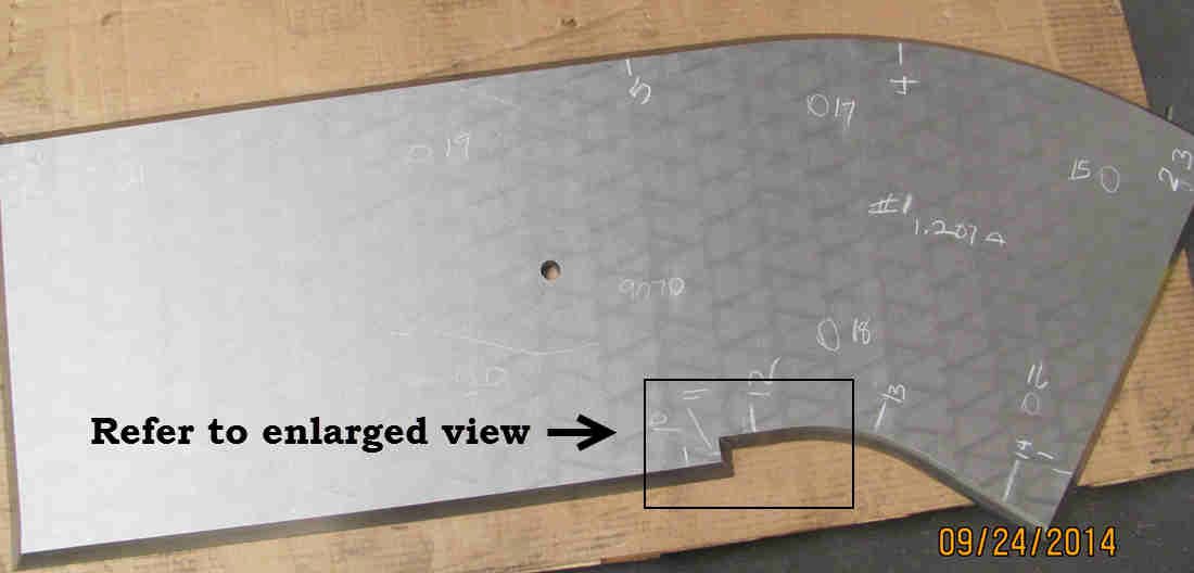
The beveled part in the picture has compound Y bevel cuts along “A”, and a Y bevel cut along “B”.
The customer said the part looked as though it had been machined!
In addition to the compound bevels in the enlarged area, the entire perimeter of the part was cut with a Y bevel.
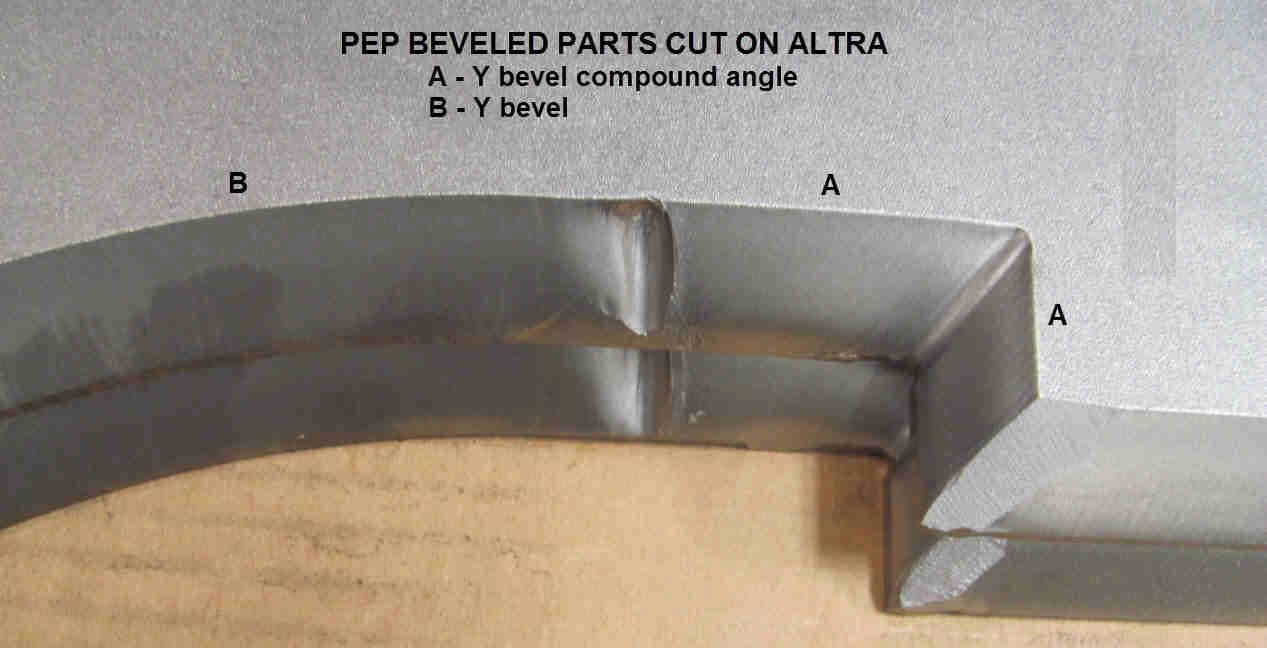
The software calculates all the angles and developed the cutter path automatically.
The compound cut along A rotates the torch at the compound angle, pierces off the part and enters the cut as a blind lead-in.
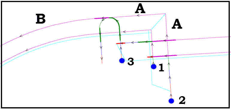
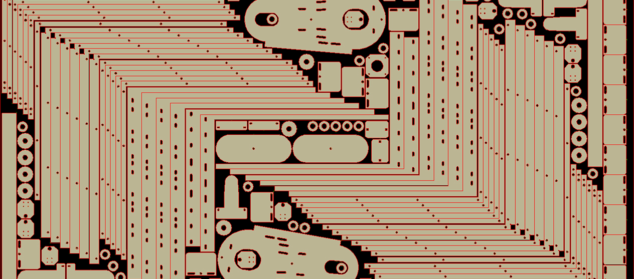
The 2D view displays the calculated cutter path in the 2D view numbering and color coding the cutter path.
The 3D view displays the actual finished part, and the finished cutter path with lead-ins.
All head freezes and cut conditions are developed automatically. The bold magenta are head freezes.
Beveling is a separate process that operates seamlessly within PEP just like converting CAD files. The beveling software creates the cutter path for the beveled part automatically after the user clicks on the geometry and then selects the bevel type, the calculations to create a beveled cutter path with the correct lead-in type and all cut conditions such as lead-ins and freezing the head are done automatically.
The PEP approach to creating the beveled path has many advantages over other methods such as; it’s very automated, easy to learn, phenominally fast, and the software displays the beveled path in a true 3D view for verification of the finished part prior to cutting the part at the machine.
There is a lot of automation to comprehend when discussing the beveling process and concepts. A full break down of the automation is quite lengthy; to make the automation understandable we will break it into the following segments and discuss a few of the most important topics.
PEP displays each task as it is entered so that the user see’s exactly what they entered in a 2D view, and then a 3D view with one click.
More than the cutter path, the user see’s the finished part along with all the tasks mentioned above in items 1 – 7.
Having all 7 items displayed is vital verification to the successful operation of the machine so that the machine does not crash, and the part is accurate.
Nest with the Best