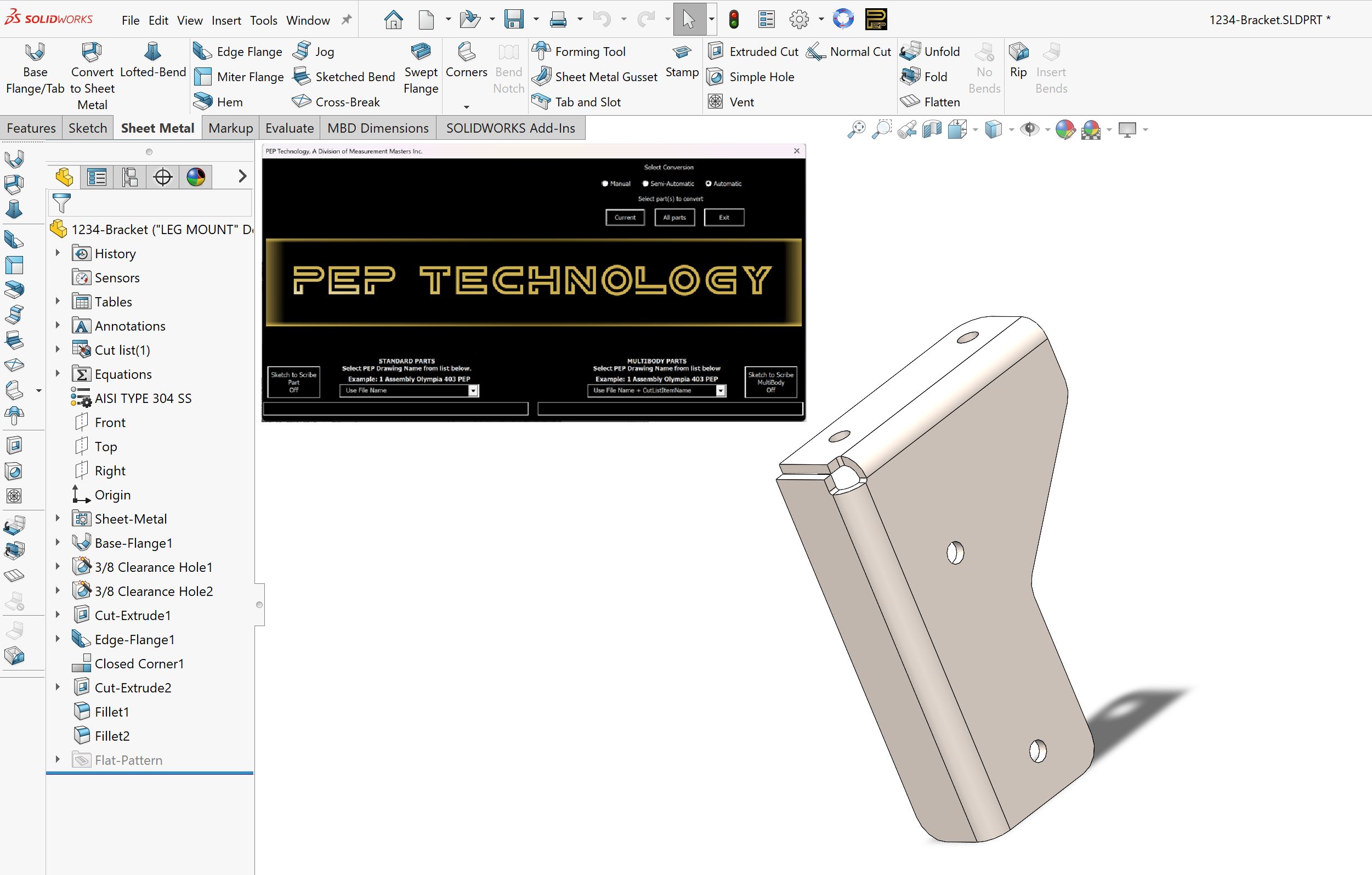
The unfolding and conversion is fully automatic!
Read The Fabricator’s article featuring PEP’s advanced automation and intelligence!
Read The Fabricator’s article featuring PEP’s advanced automation and intelligence!

ONE CLICK and you’re done
Converts SolidWorks Assemblies, Family of Parts and Single parts automatically into a finished cutter path
|
From this… |
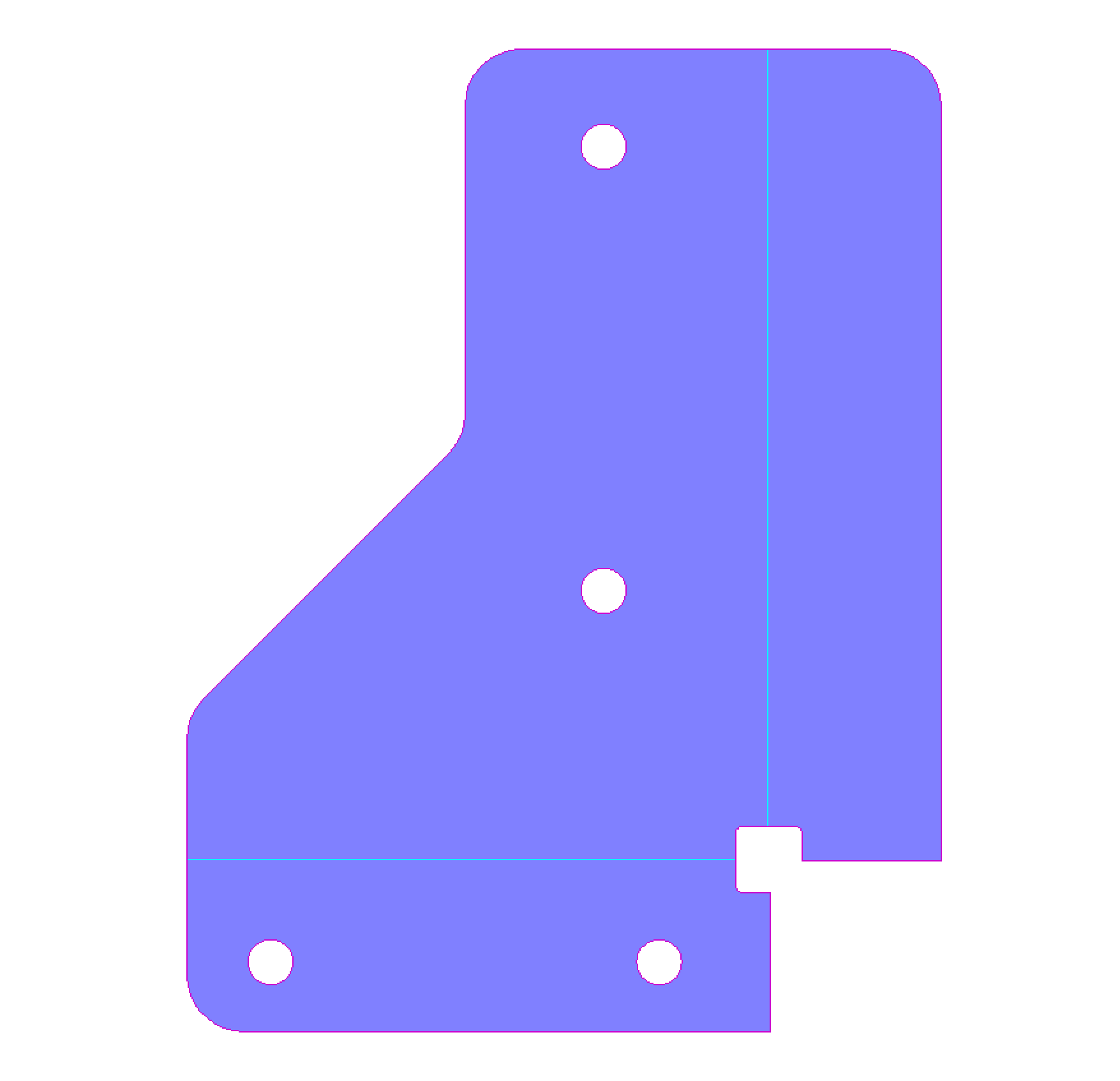
To this…in seconds! |
 |
 |
|
Display the SolidWorks drawing or assembly. |
|

The unfolding and conversion is fully automatic!
The entire assembly is analyzed and exported, only parts to be cut are converted. There is no sorting and/or locating of screws, hinges and gaskets from sheet metal parts.
The seamless integration eliminates the maintaining of old DXF files. Never cut the wrong revision of a part again!
When 3D CAD files are unfolded, CAD products (SolidWorks, Inventor, Pro-E, etc.) often replace radii along a bend with short line segment and add less than ideal bend reliefs. PEP finds and fixes automatically.
|
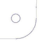
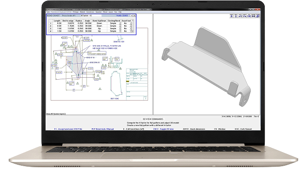
SHORT LINE EXAMPLE 50 Short Line The CAD Software saved out the part geometry with 50 short line segments that will limit the cutting speed and result in poor cut quality |
 |
|
PEP’S AUTOMATIC SOLUTION 1 Arc Geometry PEP Technology automatically finds the short line segments in the 2D part and replaces the lines with a single arc. |
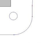 |
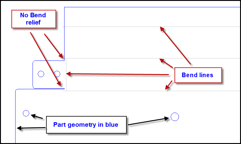
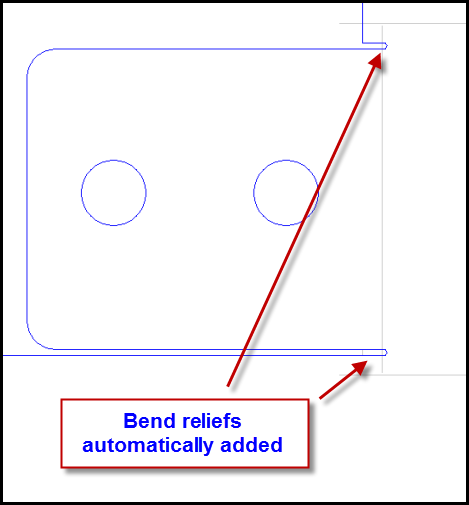
Another feature of the CAD Converter Error Correction is the detection of bend lines and the insertion of bend relief’s automatically. (Option- automatically scribe beginning and end of each bend line)
| CAD file with NO Bend Relief | The PEP Part with Bend Relief |
|---|---|
 |
 |
Rapid Access

Precision Tracking

Additional Pep Drawing Database Features Include:
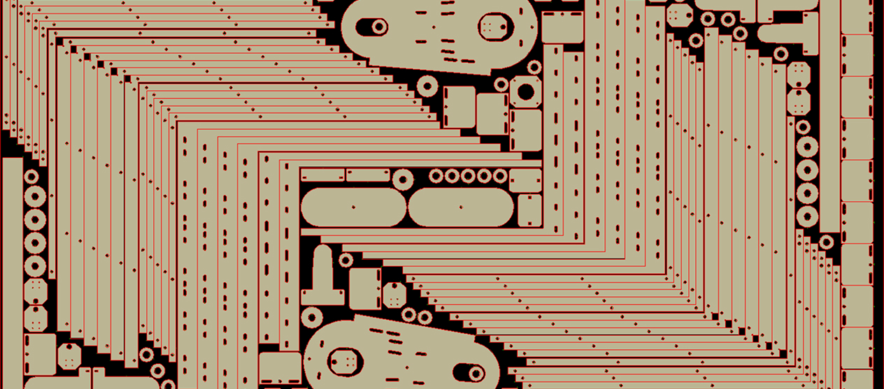
Nest with the Best

PEP’s Fully Automatic Solidworks Interface Includes: