The P.E.P. Cad Converter automatically fixed all drawing errors eliminating the need for the engineering department to correct the errors discussed in #2.
Read The Fabricator’s article featuring PEP’s advanced automation and intelligence!
Read The Fabricator’s article featuring PEP’s advanced automation and intelligence!

PEP. vs. Whitney OEM Nesting Software
All 124 nested sheets were created, sequenced, assigned lead-ins, etc. automatically ( steps 1-24 )!
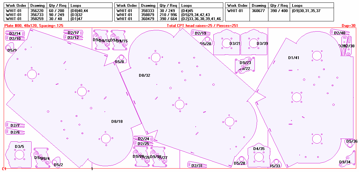
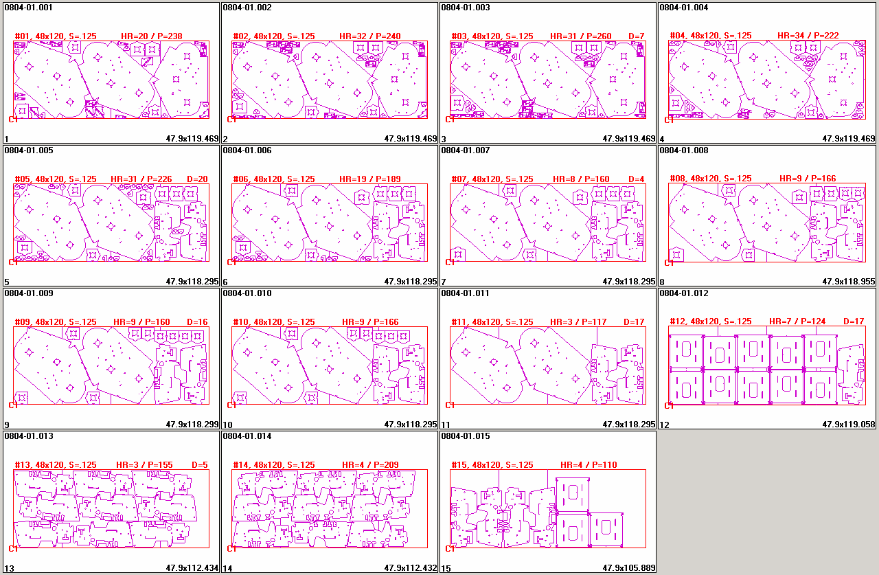
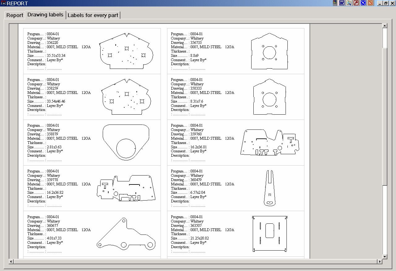
All plotted sheets display the work order #, drawing name, part quantity, cut sequence #, sub routine #, # of head raises, # of pierces, sheet size, spacing between parts, # of duplicated sheets, (i.e. #1=dup. 30).
The remaining 15 nests contained duplicated sheets totaling 94 sheets for a total of 124 sheets.
This document highlights the engineering errors, the material savings and the 30% plus increase in laser productivity attained at the W.A.WHITNEY factory while cutting a customer’s production job with the P.E.P. Technology software. The recommended software at that time was the SigmaTec software.
W.A. Whitney’s customer required 10 parts having a combined total of 3,166 parts to be laser cut.
While on site at W.A. Whitney conducting a laser presentation, a P.E.P. Technology engineer converted the customer’s drawings, nested the parts, loaded the posted files into the control and then watched as sheet after sheet were cut for more than two hour. The 2nd and 3rd shift laser operators went on to cut parts continuously for 26 hours. The results of that job are discussed in this document.
| Item | P.E.P. Technology Results | SigmaNest Results | P.E.P. Savings | |
|---|---|---|---|---|
| 1 | Engineering time to correct drawings errors | 0 Minutes | Unknown | 2 Hours |
| 2 | CAD file translation to a finished cutter path. Includes the analysis of each Cad drawing, locating of errors, correcting the error, sequencing the finished cutter path, saving of the finished cutter path. |
1 minute to automatically locate errors, fix errors & save all 10 parts as a finished cutter path. Refer to error log on page #3 to view list of fixed items; 10 duplicated geo., 2 gaps, 69 geometry combined, 2 line arc blends fixed | Unknown | 1 Hour |
| 3 | Programming time | Under 6 minutes | Est. 8 Hours | 7.5 Hours |
| 4 | Material required (11 ga. 48×120 mild steel) | 124 Sheets | 133 Sheets | 9 Sheets |
| 5 | Intersections radiused by CAM software | 4,149 | ? | $884.67 |
| 6 | Rapids/Required head raises Laser up/down time 4 seconds/rapid |
23,482 rapids / 2,079 actual head raises using PEP CPT | ? | $5,350.75 |
| 7 | Estimated Laser time to complete job | 25.8 hours | ? | N/A |
| 8 | Actual laser time to cut job start to finish | 25.8 hours | 50 Hours | 25 Hours |
| 9 | Lost machine time from damaged tips | 0 Damage Tips | Several Tips Damaged | $1,000.00 |
| 10 | Remark #1 | At no time did the laser stop cutting, dive into the material, damage a tip or lose a cut, every Every part was cut exactly as programmed. | The machine stopped continuously for multiple reasons. | |
| 11 | Remark #2 | No less than 20 Whitney employees saw the laser run and remarked that they had never seen the laser cut as fast or rapid with the head down throughout an entire nest. | A Sigmatec tech went on site to run the job and ended up staying over thru Saturday | |
| Total savings using P.E.P. on this ONE job | $6,000.00 plus | |||
The P.E.P. Cad Converter automatically fixed all drawing errors eliminating the need for the engineering department to correct the errors discussed in #2.
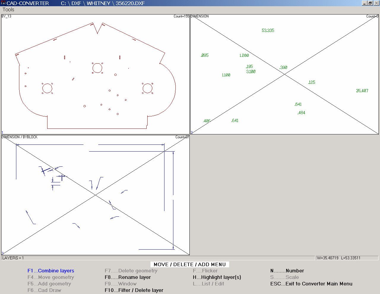
The P.E.P. Cad Converter loads the Cad file into memory and then analyzes each geometry to determine whether the geometry is part of an internal cutout or the outside boundary of the part. Having determined which geometry are to be connected, the software then checks all the part geometry for errors as defined in the conversion parameter table.
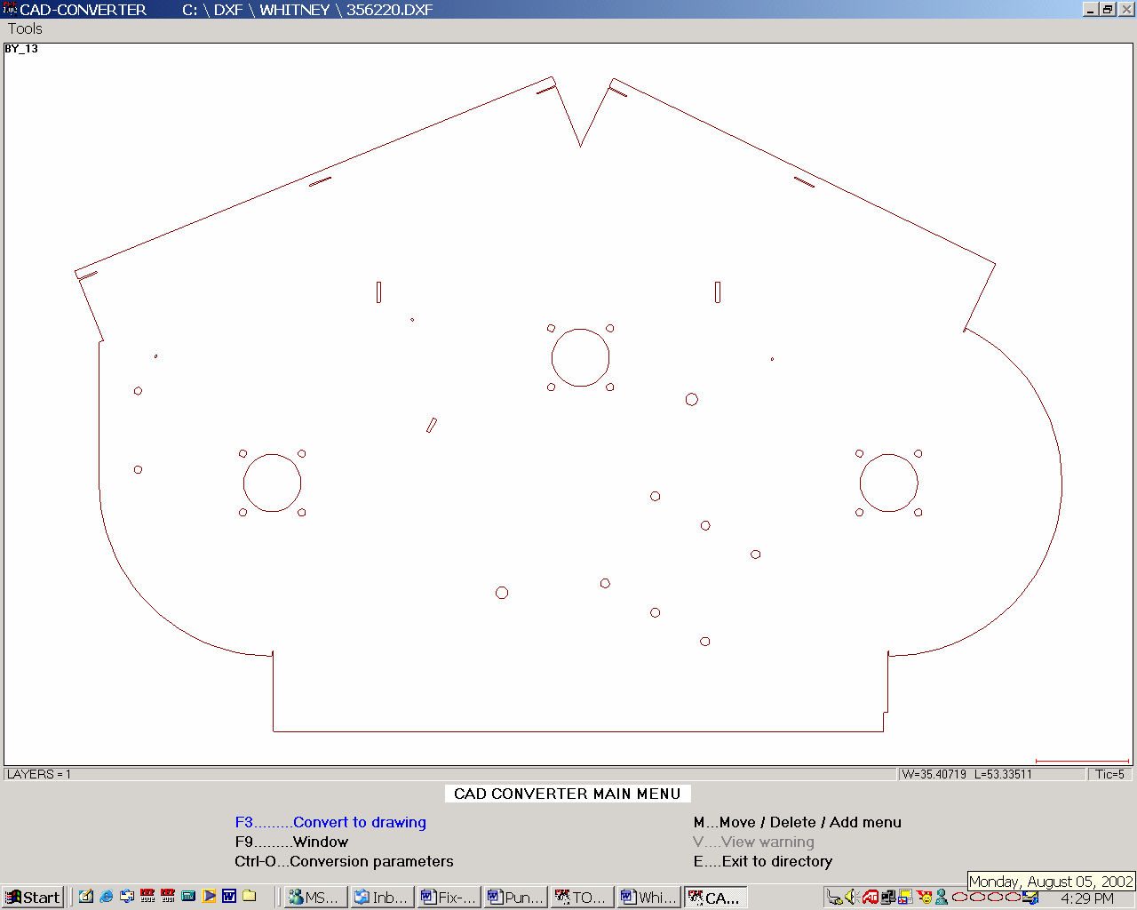
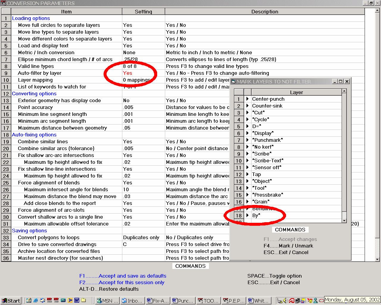
The conversion parameter fields shown below come set with default parameter settings that in most cases never need to be altered. In cases where an engineer places geometry to be cut on a specific layer, as in the case of Whitney’s customer, parameter #9 and #10 can be used to filter out un-necessary text and geometry allowing the files to be converted automatically. As circled, parameter #9 in the picture below was set to yes and the pop up window edited to include By*. This change was required because the valid geometry that engineering wanted cut was located on a layer that started with By. Adding By* to the list of acceptable layer names allowed P.E.P. to convert all 10 Cad files automatically.
|
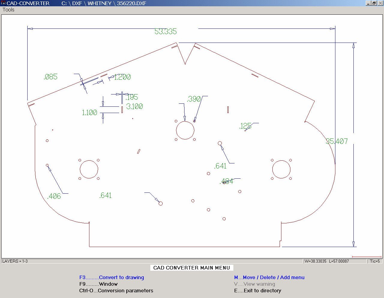
a. Each Cad file exported by engineering is loaded into memory ( i.e. drawing 356220.dxf)
|
b. Invalid CAD data is filtered out.
|
c. The valid data is analyzed
|
Although all 10 DXF files were converted automatically, the software still found and fixed all of the errors shown in columns 1 – 20 ( i.e. File name, Geos, Ellps, PlyLn, Spline, Lyrs, Polys, etc. ).
Columns 1-14 saved to the DXF log (Errors Found & Fixed by the P.E.P. Cad Converter Automatically)
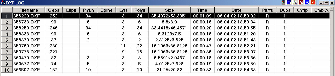
Columns 15-20 ( far right columns) are also saved to the DXF log
Automatically Without Any Operator Intervention. The Processing Of All 24 Steps ( 124 Sheets ) Took Less Than 6 Minutes.
The Nest Log below tracks the total processing time. The processing time is the total time required to perform the 24 steps discussed above.

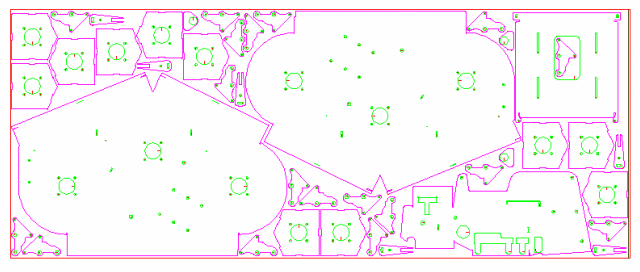
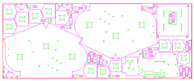
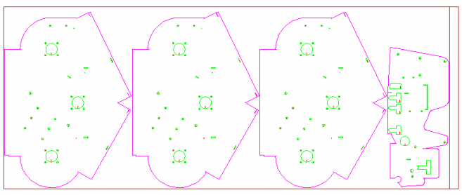
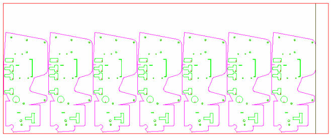
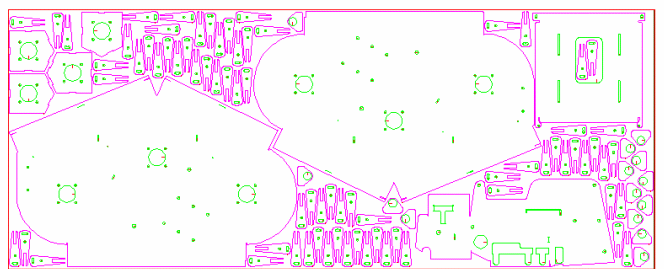
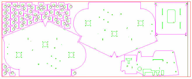
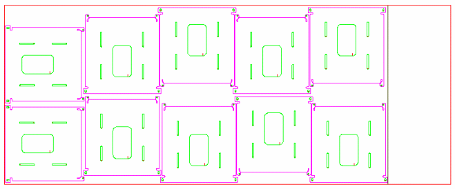
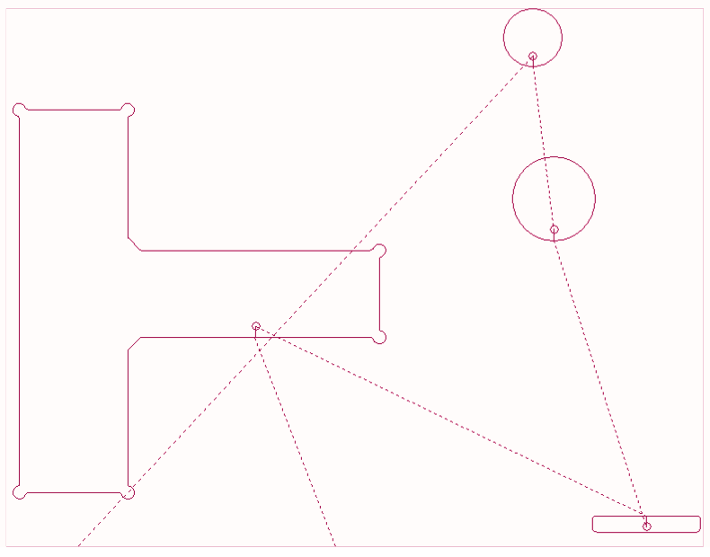
As mentioned in step 8 and 9, the software automatically sequenced the nested parts on all 124 sheets and then assigned lead-ins to the inside cutouts and the outside cutter path of each part using CPT crash avoidance logic. Of the 23,482 rapids, only 2,079 required a MANDATORY head raise be output.
As seen in fig 1 and 2, the CPT ( crash protection technology ) sequenced and assigned the lead-ins so that the laser would not have to raise the head, nor would it dive into a previously cut cutout.
| Fig. #1 | Fig. #2 |
|---|---|
 |
 |
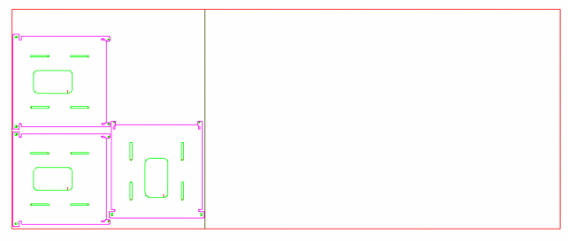
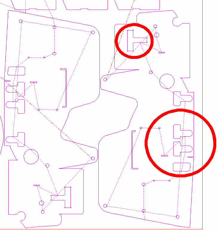
As mentioned in step 10 and 11, the software automatically radiuses intersections. In this case, the software found and radiused 4,149 intersections on the 3,166 parts. As shown in the relief cut below, the original drawing did not have a radius in either 90 degree intersect. Not radiusing the intersection of a relief will in most cases require the laser operator to slow the entire nest down, lose the cut or distort the accuracy of the intersection.
| Before | After Corner Radius |
|---|---|
 |
 |
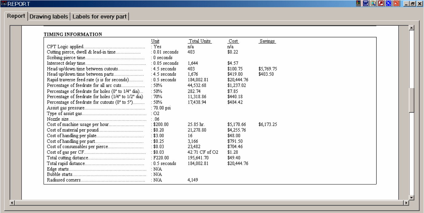
As mentioned in step 20, the software reports real time Job Costing numbers that are far more accurate than products that estimate the job.

The P.E.P. Timing information used to calculate the Job Cost.
The labels output from the P.E.P. software
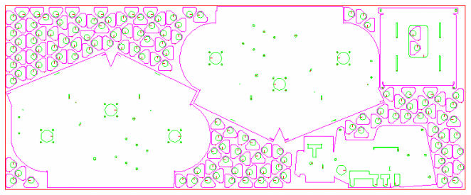
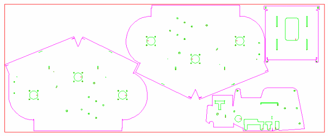
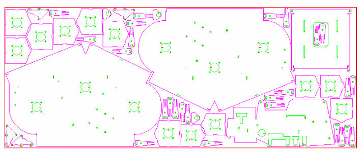
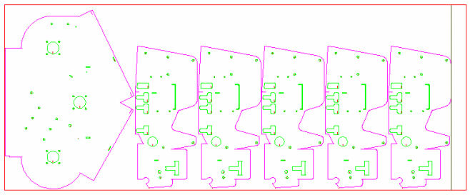
Below are the 133 nested sheets created with the Sigmanest Software