Grain FAQ: Mastering Grain Control for Optimal Nesting

Grain FAQ: Mastering Grain Control for Optimal Nesting

PEP Technology Grain FAQ

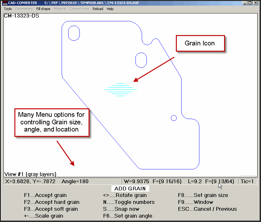
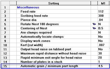
The PEP databases and software modules work interactively to control the nesting of parts that have been identified by the user as having grain.

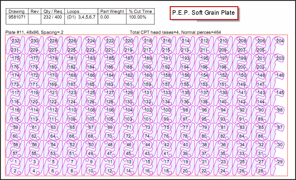
There are 3 types of Grain supported by the PEP software: Standard, Hard and Soft. Parts that have grain will be nested as follows:

  • Standard Grain – limits the nesting of the master drawing to orientations, 0 and 180 degrees. This is the default setting used when the GRAIN field is set to YES.
  • Hard Grain – limits the nesting of the master drawing to the orientation saved in the drawing database, 0 degrees.
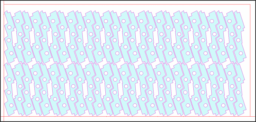
  • Soft Grain – allows automatic nesting to calculate the orientation that produces the best material yield based upon the width and length of the material using 360 degrees of rotation. All parts will be nested at 0 and 180 degrees of the calculated angle.

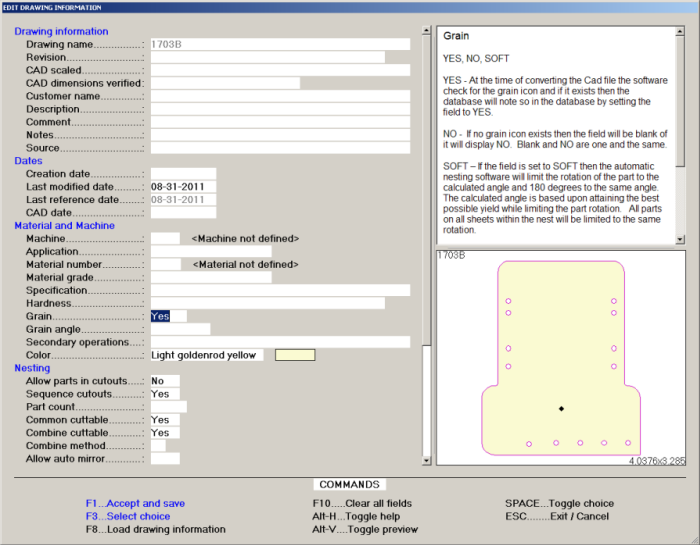
For example, if the best yield is calculated to be 20 degrees, automatic nesting will nest the parts at 20 and 200 degrees.

The user sets the grain type in the drawing database field shown on the screen to the right.

Pressing the space bar in the field toggles the input field showing: NO, YES, HARD, SOFT.

The automatic nesting software uses the database field to control the part rotation on ALL nested plates within the same nest.


Parts with grain are saved to the master drawing database with the grain icon displayed below in the picture.

It is the user’s responsibility to locate, rotate and size the grain icon at the time of converting the CAD file into a PEP drawing, and to select the type of grain in the grain field as discussed in the previous section.

The CAD converter software calculates the angle of the icon and saves the starting angle to the drawing database as the part is converted.

The Grain icon is saved as DISPLAY ONLY geometry in the drawing and will be discarded by the post processor at the time of posting. As such, the grain icon is displayed in previews, nests, labels and in plots.

Once the grain is set by the user, the software STOPS both Automatic and Manual Nesting from rotating the part to an angle other than the angle allowed. We know of no other competitors having this capability.

Soft Grain can be added to any part. Once set, automatic nesting will nest the part at the best angle FOR MATERIAL YIELD, holding that angle throughout all the plates in the nest.

Examples of Soft Grains below:

Yes- Setting Hard grain will not rotate the part to 180 degrees from the original angle

In the CAD converter, two mouse clicks bring you to this screen.

Yes- the CAD converter has an option described below.

Grain Input Field Settings

    • Part rotation for individual drawings is stored in the state and angle grain fields of the PEP Drawing Database.
  • The grain state field will track 4 different states as explained in the grid below.
  • The grain angle field accepts all angles.
  • A copy of the grain fields as well as other pertinent drawing database information is saved inside each nest at the time the drawings are copied into the nest.
  • The automatic and manual nesting modules use the drawing data to display the state and the angle for each drawing when accessing the Automatic Nesting Main Menu.
  • The grain data controls part rotation in both the Automatic and Manual mode.
  • The grain “state” (rotation orientation) and the grain “angle” saved to each nest works seamlessly to control part rotation when automatically and manually nesting parts.
    • Automatic nesting –All approaches and methods of automatically nesting utilize the individual part data to control the state and the angle of parts as they are nested.
    • Manual nesting – if the grain rotation is set, the rotation keys limit the rotation as defined in the grid below.
  • Because the nesting modules are using a copy of the drawing database information, the state and angle of each drawing as it relates to grain are static and not dynamic, this is intentional.
    • Static – means that the angle is unique to the nest and will not change even if the master drawing is changed.
    • Dynamic – means that changing the angle orientation in the master drawing database will not change the angle of a nested part until the user selects to update the drawing using Ctrl-U. If the angle were to be dynamic and the user did not re-open the nest, the parts could overlap without the user being made aware of it.
  • To ensure that nested parts are nested at the correct grain rotation, the user is prompted at the time of converting a newer revision that the drawing exists, and that the drawing has been nested. It is the user’s responsibility to update nests with the newer revision when it is appropriate. To assist the user, the Cad Converter software:
    • warns the user when converting a revision that the drawing already exists
    • displays a picture of the existing master along side the new part being converted
    • displays all the drawing data of the previous master drawing.
  • If a revised drawing has the grain state or angle changed, the user is warned at the time of converting the Cad file to a PEP Drawing.
  • The Grain Field can be accessed at all the drawing database pop up screens such as:
    • The Cad Converter “Drawing Data” screen.
    • All drawing directories by pressing Ctrl-D.
  • The grain rotation can be set as follows:
    • AUTOMATICALLY
      • At the time of converting the Cad file with the Cad Converter the software checks the drawing layers for the PEP grain symbol, if the grain symbol exists then the software automatically calculates the angle of the lines that make up the grain symbol and:
      • saves the angle to the drawing database
      • sets the grain field to YES
    • MANUALLY at the Autonesting Main Menu The grain angle can be set at the Automatic Nesting Main Menu when nesting parts. When setting the grain angle the software will save the angle to the nest data, but not the master drawing database. To change or cancel the grain angle for the current nest select F4..Bestfits and then Delete bestfits.
    • MANUALLY using Ctrl-D at the Drawing Data pop up
      • The grain angle can be set and edited at the drawing data input screen. When editing the drawing data screen the user must be aware of the following:
      • the part will be nested at the master drawing orientation as shown in Review PLUS the angle entered into the angle field.
      • when manually entering the angle the grain symbol will not be created, if the symbol already exists the software does NOT change it. We recommend reconverting the file with the “RECONVERT HIGHLIGHTED” option on the TOOL option list.
  • Setting the grain symbol:
    • When manually locating the grain symbol on the part, the user needs to be aware that the grain symbol must be located entirely on the part in an area that does not overlap another cutout or text.
    • The size of the grain symbol is not important, the state and angle are documented in the drawing and the nest, therefore the symbol is a visual aid for the user. The grain symbol must not touch the part geometry or it will effect the accuracy of the finished part.
  • The grain STATE can be set as follows:
Grain Type Description Special Notes
Blank Implies no grain, the part can be parked at any angle  
Yes The part has grain and can be parked at the specified angle or 180 degrees to the initial angle.  
No the part can be parked at any angle  
Soft All the required part must be parked at the same angle or 180 degrees to that angle. The calculated angle is based upon attaining the best possible yield while limiting the part rotation. All parts on “all” sheets within the nest will be limited to the same rotation. Ex. 42 deg. & 222 deg.
Hard The part must be nested at the angle specified, nesting at 180 degrees is not allowed. Ex. 0 deg.

The Automatic Grain field in the material database can be used to control the way the nesting logic rotates parts to be nested automatically.

The automatic grain field works exactly like the grain field does when set to STANDARD grain without the user having to add the grain icon and or set the grain field for each part.

The automatic nesting software working seamlessly with the material database extracts the minimum part length from field #15 and compares the set distance to both dimensions of each part.

Leaving the Automatic Grain field blank or set to 0 will result in the automatic grain feature not being invoked.

Automatic Grain will have NO effect on the nesting of parts when both the X & Y dimensions are greater than value set in field #15.

Parts that have one dimension that is less than the value in field #15 will be nested with STANDARD grain with the longer rotation of the part nested across the horizontal X axis automatically.

We recommend that small parts with both the X & Y dimensions being less than field #15 should be tabbed so that they do not tip after being cut.

Typical two part nest, shown without auto grain, then with auto grain

Obviously holding one rotation for small parts will increase the area needed for the nest. However, it is usually a small trade-off, when compared with engineering time to add grain or tabs, and the resultant cleanup costs.

Auto Grain also works with Automatic Combine cutting!

Yes. Bullet was enhanced to display the autograin setting held in from the material database. The user is able to edit this value for this nest.

For more information on grain or PEP Technology, call us at 949-753-7878, or email [email protected].

PEP Technology is exactly what you need

Take Control of Your Profits Today

Nest with the Best

cta-wrapper-bg-1